
![]()
This subject can be a pretty daunting, so to simplify let’s start by inventing our own colour space. We’ll call it RAINBOW!
RAINBOW colour space is going to be very simple and only represents 7 possible colours, with corresponding values of 0.1 – 0.7.
0.1 = Red, 0.2 = Orange, 0.3 = Yellow, 0.4 = Green, 0.5 = Blue, 0.6 = Indigo, 0.7= Violet
An image file that is encoded in RAINBOW colour space will simply contain a long list of the above numbers (one for each pixel), and hopefully a bit of metadata noting that is is in RAINBOW colour space. When you open the file, your computer will read the metadata, seeing that it is in RAINBOW, and then start reading the image data. If a pixel has a value of 0.1, the computer will refer to RAINBOW in it’s list of colour spaces and find that 0.1 should be red. That pixel will then be displayed as red on your monitor, and so on. If the metadata is missing then the computer will take a guess as to the colourspace and most likely assume sRGB (the most common colour space for computer monitors).
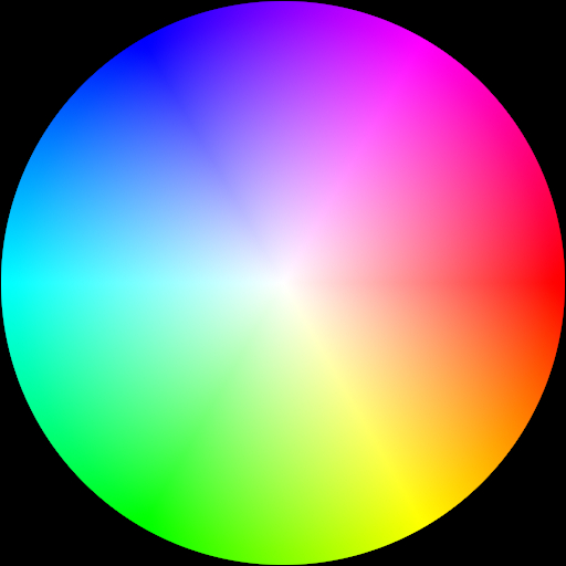
Colourwheel in sRGB colour space

Colourwheel in RAINBOW colourspace

Colourwheel in RAINBOW colour space, but incorrectly interpreted as sRGB
From the above images you can probably see that our RAINBOW colour space has some pretty crippling limitations. It can only represent seven solid colours with no gradation between them. It can’t display black or white and has no latitude for hue or saturation. It’s possibly the worst colour space ever invented. Shame on me! It does however illustrate my point that a colour space is just a way of numerically representing colours that some sort of device can interpret. Different colour spaces are kind of like different languages, and we need to be able to interpret between them. You can also hopefully see that there are limitations. A certain colour that can be represented by one colour space, my not be accurately reproduced by another. The range of values that can be represented are known as the colour space’s gamut (not to be confused with gamma). RAINBOW can be said to have a very small gamut.
So why don’t we just chose one colour space for everything?
Colour spaces are mostly designed to bridge the gap between software and hardware. CMYK for instance, stands for Cyan, Magenta, Yellow, blacK, and is used in print, where inks are used to block wavelengths of light – You start with a white sheet of paper (white is a combination of all wavelengths of light) and deposit inks that selectively block wavelengths, changing the reflective properties of the paper. This is known as colour subtraction. However devices that emit light (TVs, projectors, computers, phones, etc.) operate using colour addition. Most commonly they will emit a combination Red, Green, and Blue wavelengths of light (RGB), which when added together make white light, or any number of colours within that device’s gamut. If you tried to feed RGB information into your printer it just wouldn’t work. For one, (most) printers don’t have red, green and blue inks, and more importantly because the physics of the mediums are different. The same is true of trying to feed CMYK colour into an RGB based device. This is an extreme example, and as compositors we’re hopefully not going to be dealing with CMYK colour any time, but it’s important to understand that more often than not it’s the hardware that decided which colour space something will be in. This is true of all of the many variants of RGB colour too. The sensor in a camera from one manufacturer will likely respond differently to light than that of another manufacturer, and these will be different again to the hardware of a monitor or projector. All of these devices need their own custom colour spaces that can be translated between, so that an image from one piece of hardware can be displayed faithfully by another. Consumer digital cameras even have dedicated chips inside of them that do these conversions internally so that the image from the sensor can be displayed by the screen, and saved as a file that can be read directly by your computer. There is also the matter of the storage of data within an image file – If you read my article on floating point colour I mentioned that in 8bit colour a gamma was applied to the image so that the ‘more important’ data had the lion’s share of space in the file, a sort of rudimentary file compression if you will.
There are also colour spaces that are not based on hardware, but are designed to make image data easier to work with inside of a computer. Linear RGB (Nuke’s native working colour space) is one example of this, as is HSV (Hue Saturation Value) and XYZ, which I believe is the only colourspace who’s gamut extends beyond that of human vision.
Channels
An interesting point of difference between our RAINBOW colour space and most others is that RAINBOW only had one set of values, or one channel. Many other colour spaces such as sRGB and the other RGB derivatives, HSV, and XYZ, have three channels. CMYK has four. There’s no scientific reason why a colour space should have a certain number of channels, except to serve the hardware that created it, the hardware that displays it, or the computational efficiency in handling the information. Real world light isn’t necessarily comprised of a combination of red, green and blue; that’s just the way that our display technology fools our eyes onto seeing a certain colour.
Nuke’s colour workflow
Nuke natively works in linear RGB colour space, converting all incoming material to linear on the way in, and then before rendering, converting the output to your desired output colour space. In linear colour space the scale of brightness works on a linear scale, eg. black is 0 and 1 is twice as bright as 0.5, 2 is twice as bright as 1, etc. This makes mathematical operations on an image very simple and predictable, giving consistent results regardless or the source’s colour space. This workflow in made possible by the fact that Nuke works in floating point colour depth, making colour space conversions almost lossless (having negligible effect on image quality). Nuke also uses a viewer LUT (look up table). Computer monitors don’t expect a linear input so the viewer LUT converts the image that you’re working with into something that your monitor will understand. This can be a regular sRGB conversion, or something that has been specifically set up to mirror the way an image will look when projected in a cinema. The viewer LUT has no actual impact on the image itself, and is never ‘baked in’, it is just to help display the image correctly while it is in the Nuke environment.
Nuke’s linear approach solves a host of workflow issues, but there are some circumstances where it is beneficial to work in an images native colour space, namely when dealing with noise or grain. The nature of digital noise from a sensor, or grain on a piece of film is that it is distributed in a fairly way across the image regardless of the image’s brightness. When we convert these images to linear colour space, although the image itself becomes linear, the noise becomes non-linear. It is far easier to add/remove/filter noise when it is linear in the same way that it’s easier to deal with an image when it’s linear. It just so happens to be that the two are never both linear at the same time.
There are other operations where Nuke will do colour space conversions inside of a node. The HSV tool is an example of this. As the name suggests, it does an HSV conversion (Hue, Saturation, Value) to allow you to adjust these channels individually, and then converts back to linear all in the one node. The basic Nuke keyer does kind of half of an HSV conversion too, in order to supply a greenscreen or bluescreen key (I’ll expand on that in another article).
Functions and LUTs
Colour space conversions can come in the form of either a mathematical function or a look up table (LUT). S = max(R, G, B) – min(R, G, B) is the function to convert RGB values in to the saturation value of HSV. In plain English this function says ‘the saturation will equal the difference between the the brightest and darkest RGB channel’. So if you have an RGB value of [0.1, 0.8, 0.5] the saturation will be 0.8 (the brightest) minus 0.1 (the darkest) giving 0.7. Functions are great because they allow you to calculate and number, giving a result that is just as accurate as the input. LUTs on the other hand consist of a table of input and output values. A LUT would just say RGB [0.1, 0.8, 0.5] = S [0.8], without giving the formula that explains how one equals the other. A LUT will contain a huge array of these source and result values, but if the exact number that you’re looking for isn’t there then it’ll just jump to the nearest one. LUTs are lossy for this reason, meaning that they can degrade the quality of the information in an image, however LUTs are a necessary evil because not all conversions can be explained by a function, or sometimes that function is so complex that it’s computationally too expensive to be useful. The conversion between Linear RGB and sRGB is one such example of something that can not be explained by a function, but Nuke kind of cheats with this one, by just simplifying it into Linear = sRGB^1/2.2. This function is a very rough approximation of the sRGB model, but deemed to be close enough since in this case the benefits of using an inaccurate function outweigh those of using an accurate albeit lossy LUT. Although it is highly likely that somewhere along the colour pipeline a LUT will be applied, is is better to avoid them in the compositing workflow except for display purposes (by this I mean Nuke’s viewer LUT, which has no impact on the final image).

Pingback: Gamma & contrast | The Compositor Mathematic
hello! i love your blog, it has some simple to the point explanations of pretty complicated things! Please post more! Also wanted to ask if it possible to have a precise gamma conversion from linear into rec709, applying the precise function of the rec709 space gamma? Surely it should be possible in nuke?
Hi Stepan,
Thanks, it’s been a long time since I’ve written an article here. Unfortunately it takes a long time to research and write on each topic and life gets in the way!
Nuke has built in conversions (in the colorspace node, and in the read & write nodes). Conveniently the gamma curve is specified in the node – ‘rec709 (~1.95)’ So the linear -> rec709 conversion is a gamma correction of approximately 1.95. That is approximate though, so entering that in a gamma node won’t give you a perfect result.
Here is the exact formula, where ‘Value’ is one of the colour channels (as taken from this Nuke forum thread)-
So here’s a Nuke expression applying that formula –
I hope that helps.
-Gene
Ah amazing! Thank you for that! Basically i’m a colourist that does a little bit of nuke work as-well. The main problem is that I am completely self taught and a lot of the times it’s a little bit confusing trying to figure these things out. A lot of the times if you understand the maths behind something but don’t know code or expressions it’s hard to understand them. I’ve noticed that your last blog post was quite some time ago, but the topics that you have covered here are very throughfully explained, which is pretty rare to find! Hope you will have some inspiration to write here again!